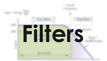
Filters are quite an important application in Electronics. You may want to filter out lower or higher frequencies, or perhaps a band in the middle. This is very important in audio systems (think bass etc), but also in for many other electrical components.
Passive Low pass
Low pass filters simply let the low frequencies “pass” while not letting through higher frequencies.

A capacitor has the function

or 1/(ωC). (ω = 2 * pi * f)
You can see if f increases the bottom part will get larger and as a result Xc will get smaller and smaller. This will make the capacitor have a lower impedance and thus a smaller voltage drop (X = U/I -> U = X * I) which means that Vout will be lower when increasing the frequency. This is the basic idea of a filter.
Gain

The difference between Vout and Vin is often defined in Gain (dB), you might recognize this scale from how loud sound is, but it is important to know that we are talking about voltages here, not directly sound.
Gain is defined as 20 log(Vout/Vin) where the 20 comes from the 45 degree slope that can be seen at the right of the image. 45 degrees ends up at -20dB/Decade where a decade is a factor 10 on a logarithmic scale.
normal: 1, 10, 100, 100
decade: 1, 2, 3, 4
The cutoff frequency is the frequency at which
Cutoff frequency
The cutoff frequency Fc is the frequency at which the gain is -3db and the slope is exactly 45 degrees. This is is ultimately the magic that decides where your filter should start cutting off.
The cutoff frequency is defined as follows:

Where R is the resistor’s resistance and C is the Capacitance of the Capacitor
You will see this RC factor come back below
Time constant
The time constant t (greek tau) is defined as R * C.
This time constant is an indicator for the time needed to charge the capacitor. To be exact the time from 0 volts to approximately 63.2% (1-1/e) of the value of an applied DC voltage.
